 Product Overview
Ceyear 3674 Series vector network analyzer is the peak of technological innovation, which can easily deal with the severe challenges brought by semiconductor chip testing, material testing, antenna testing, high-speed cable testing, and microwave component testing and so on. Excellent RF characteristics, flexible hardware configuration and rich software functions complement each other; only one connection can be completed in a variety of measurement tasks. Innovative human-computer interaction design can help you complete the required measurement Settings quickly and conveniently, and the large touch screen brings you a flexible and efficient operation experience.
Key Features
Pulse S-Parameter Measurement
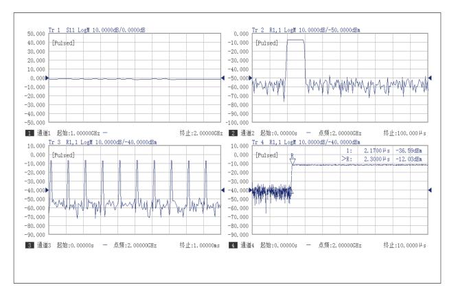
The system is equipped with a built-in 4-channel pulse generator, used for internal source modulation and IF gate control, with outputs available on the rear panel. The pulse width and delay of each channel can be set independently.
The source modulation options include rear-panel input, internal pulse generator, or normally open/closed states. Users can modulate the vector network analyzer's source using an external pulse, or keep it in continuous wave (CW) mode and perform measurements through trigger synchronization.
This functionality provides strong support for testing T/R modules, antenna transceiver components, and other pulsed RF devices.
|
|
|
Scalar Measurement and Analysis of Mixers/Converters
The system provides comprehensive configuration options for mixer/converter characterization, supporting dual-stage local oscillators (LOs) and external LO source input. It supports various sweep types including linear sweep, power sweep, and segment sweep.
With simple setup, the system can automatically perform complex calculations involving frequency multiplication, division, and relationships between RF, dual LOs, and IF signals.
It also supports configuration of key parameters such as source port power, LO port power, attenuation settings, and power sweep characteristics, enabling efficient and accurate scalar analysis of mixer and converter devices.
|
Vector Measurement and Analysis of Mixers/Converters
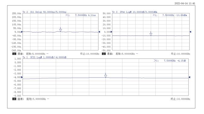
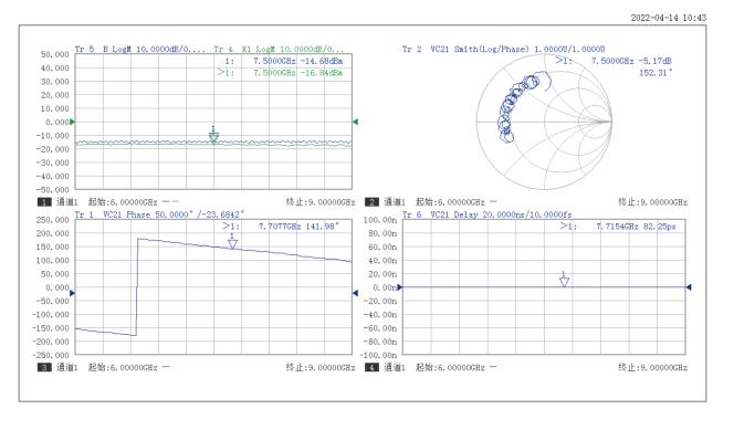
The system provides comprehensive measurement capabilities for the magnitude response, absolute phase, and absolute time delay response of mixers / converters.
During calibration, a dual-mixer setup is introduced to perform frequency conversion on both the reference path and the calibration path. The added calibration mixers must exhibit the same frequency conversion characteristics as the device under test (DUT), and they must also meet the requirement of reciprocal conversion characteristics to ensure accurate vector calibration.
With this approach, the complete complex (magnitude and phase) characteristics of the mixer / converter can be measured in a single connection, delivering high-accuracy amplitude and phase measurements. This enables precise characterization of advanced mixer and frequency conversion devices in R&D and production test environments.
|
|
|
Gain Compression Measurement
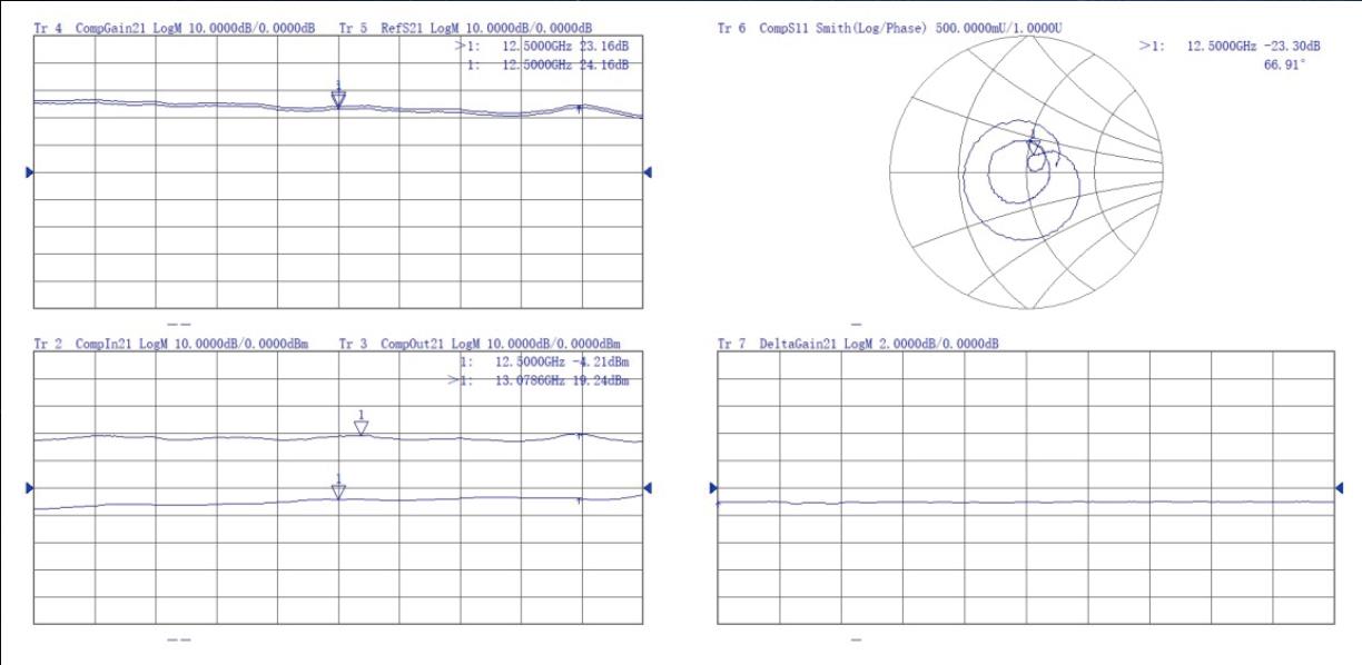
The gain compression measurement function enables the complete characterization of active devices within their operating frequency band, including parameters such as linear gain, compressed gain, input power at compression point (P1dB), output power at compression point, and linear input matching.
All these compression-related parameters can be obtained through a single connection and a single calibration, improving test efficiency while ensuring high measurement accuracy. This feature is particularly useful for evaluating the nonlinear behavior of RF components such as amplifiers and T/R modules under real-world operating conditions.
|
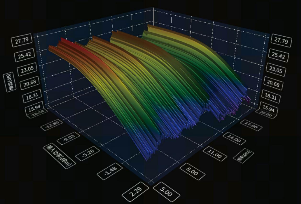
3D Plotting for Gain Compression Sweep
The system provides a 3D view function to better visualize the performance of the device under test (DUT) under various excitation conditions. In addition, it supports frequency slice and power slice views, allowing intuitive display of the DUT’s characteristics at each frequency point and power level. This comprehensive graphical representation enhances analysis accuracy and facilitates in-depth understanding of device behavior across both frequency and power domains.
|
|
|
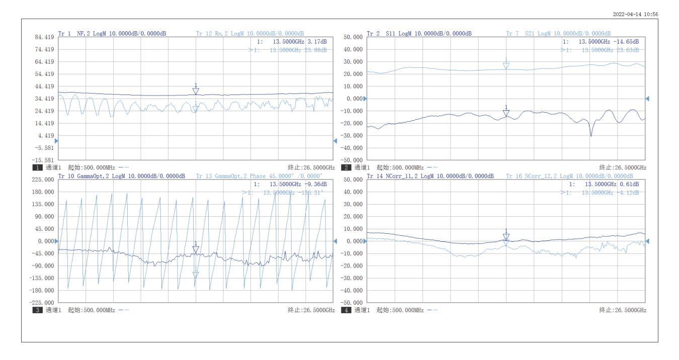
Noise Figure Measurement
The system supports simultaneous measurement of multiple parameters, including S-parameters, noise figure, noise parameters, gain compression, and conversion gain, all with a single connection.
Based on the cold-source noise figure measurement method, it enables accurate testing of noise figure and noise parameters. By constructing an advanced noise correlation matrix model and combining it with the precise S-parameter calibration of the vector network analyzer (VNA), the system is especially suitable for the accurate characterization of devices with low noise figures.
With a maximum measurement dynamic range of up to 55 dB, this solution is also well-suited for testing devices with high gain, ensuring reliable and high-precision results across a wide range of applications.
|
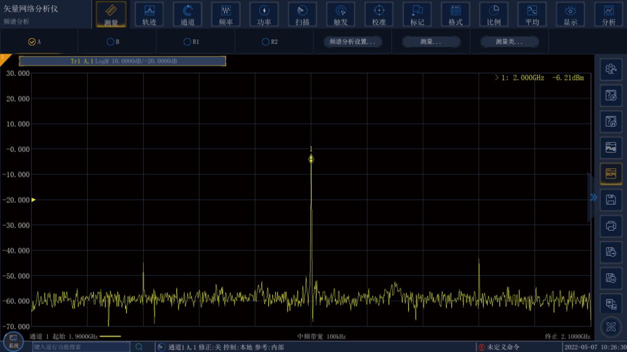
Spectrum Measurement and Analysis
Each port of the vector network analyzer (VNA) is capable of measuring both the input and output spectra of the device under test (DUT). The system can quickly identify spurious emissions and harmonics of the DUT, even under narrow resolution bandwidth (RBW) conditions.
For testing active devices, the spectrum measurement function provides enhanced parameter analysis. A single instrument, with one connection, can perform standard S-parameter measurements along with targeted detection of spurious and harmonic frequencies.
Combined with comprehensive ratio and absolute error correction techniques, this functionality delivers highly accurate spectral measurements, improving the reliability and efficiency of RF and microwave component characterization.
|
|
|
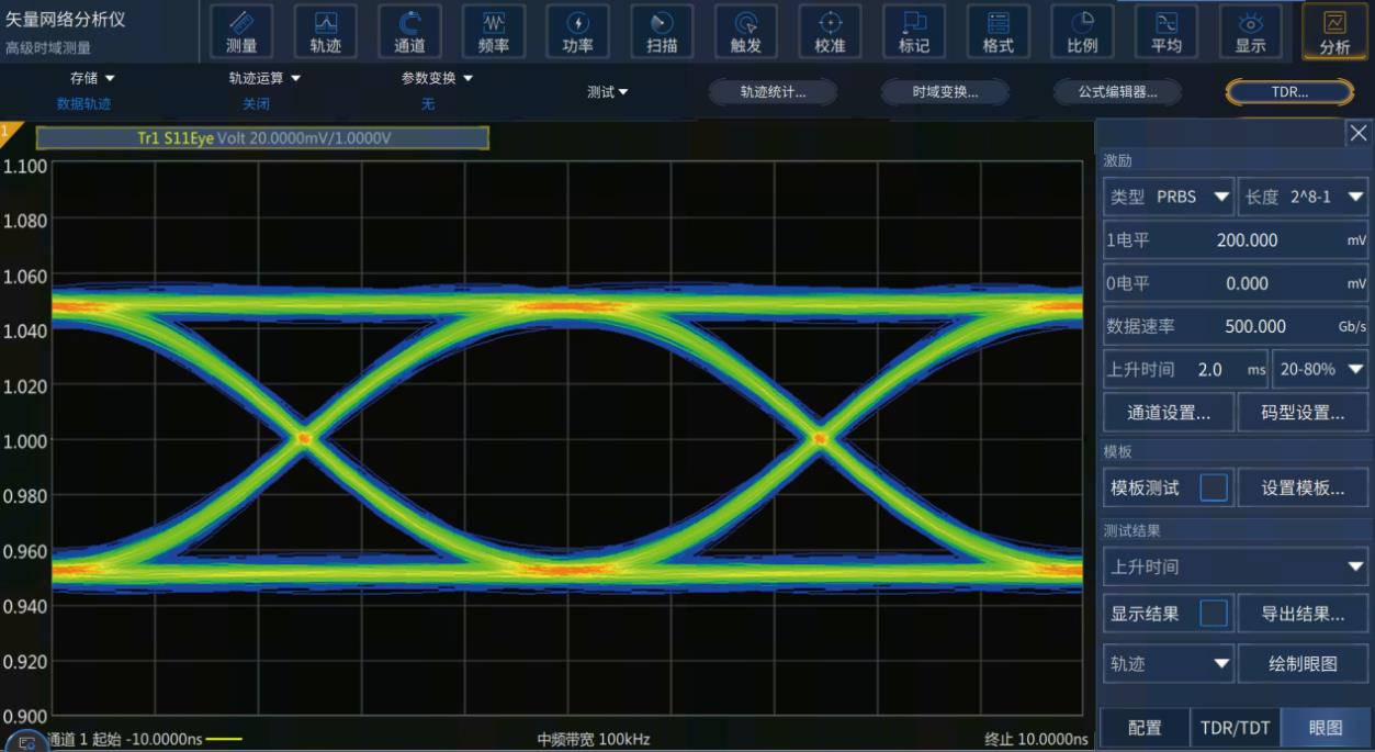
Signal Integrity Measurement and Analysis
The system offers powerful signal integrity analysis capabilities with micron-level spatial resolution. A single view enables simultaneous time-domain and frequency-domain analysis, allowing precise detection of impedance variations along transmission lines.
The instrument also supports convenient near-end and far-end crosstalk measurements, which are essential for evaluating the level of interference between multiple transmission lines.
Equipped with an Advanced Time-Domain Analysis Option, the system can generate and analyze virtual eye diagrams based on network parameters. According to various high-speed digital communication standards, predefined eye diagram templates can be used to perform efficient Pass/Fail testing, significantly improving evaluation speed and accuracy in signal integrity validation.
|
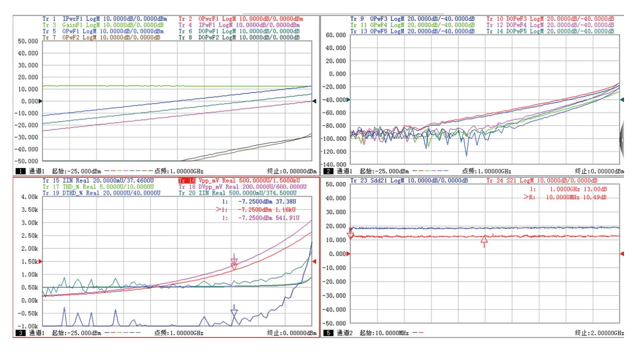
Total Harmonic Distortion (THD) Measurement and Analysis
The system supports wideband testing and is capable of analyzing key parameters under true differential excitation, including input/output power, gain, and total harmonic distortion (THD). This functionality simplifies the complexity of harmonic performance testing for differential devices.
A single calibration can correct errors across multiple channels simultaneously, improving measurement efficiency and accuracy. The configuration and editing of measurement parameters can be performed via XML files, enabling one-click parameter import and setup for streamlined workflows and enhanced repeatability.
|
|
|
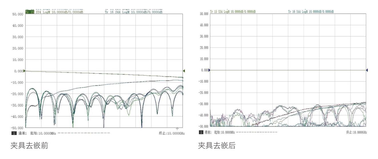
Automatic Fixture Removal
For testing non-standard connectorized devices, such as packaged microwave components or on-wafer devices, direct connection to the vector network analyzer (VNA) is often not feasible. Fixtures are typically used to interface these devices with the VNA, but they inevitably introduce measurement errors.
The Automatic Fixture Removal function enables the extraction, storage, and de-embedding of fixture parameters. This allows the system to effectively eliminate the influence of the fixture, thereby obtaining the true characteristics of the device under test (DUT). This feature significantly improves measurement accuracy and simplifies the testing process for complex or non-standard microwave components.
|
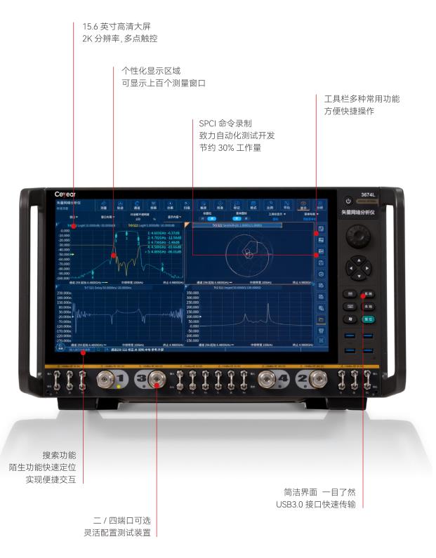
Ultimate User Experience
The interface is designed to be simple and intuitive, making it easy to operate and significantly improving testing efficiency.
|
|
|
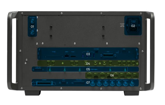
Rich and Flexible Peripheral Interfaces – Practical and Versatile
-
10 MHz External Reference Input/Output Interface
-
110V/220V Auto-Sensing Power Input
-
Removable CPU Module, Configurable with hard drive, LAN, DisplayPort (DP), USB, and GPIB interfaces
-
Excitation Output, Local Oscillator (LO) Output Interfaces, Provide flexible measurement configurations to meet a variety of test requirements
-
External IF Input Interface, Pulse Input/Output Interfaces
-
Bias-T Configuration Input Interface
-
Automatic Test Interface, Trigger Input/Output Interface, Noise Source Power Interface
|
1. Pulse S-Parameter Measurement
This function provides strong support for the testing of T/R modules, antenna transceiver units, and other pulsed RF components. The system can either modulate the vector network analyzer's (VNA) source using an external pulse, or operate in continuous wave (CW) mode with measurements synchronized via a trigger signal.
This flexible configuration enables accurate characterization of pulsed devices under real-world operating conditions, making it ideal for applications in radar, communications, and aerospace & defense systems.

2. Measurement and Analysis of Mixer / Converter Characteristics
The system provides comprehensive configuration options for testing mixers and converters, supporting dual-stage local oscillators (LOs) and external LO source input. It also supports various sweep types, including linear sweep, power sweep, and segment sweep, to meet diverse test requirements.
With a single connection, the system can perform complete complex characteristic measurements of mixers or converters, delivering high-accuracy amplitude and phase measurements. This enables precise evaluation of frequency conversion performance, making it ideal for R&D and production testing of RF and microwave components such as upconverters, downconverters, and transceivers.

3. Application of Noise Figure Measurement
Based on the cold-source noise figure measurement method, the system enables accurate testing of noise figure and noise parameters. By constructing an advanced noise correlation matrix model and integrating it with the precise S-parameter calibration of the vector network analyzer (VNA), it ensures high measurement accuracy.
This solution is especially suitable for characterizing devices with low noise figures, such as low-noise amplifiers (LNAs) and RF front-ends, providing reliable data support for performance evaluation and design optimization in communication systems and microwave circuits.

4. Application of Signal Integrity Measurement
The system offers ultra-wideband coverage with micron-level resolution, enabling precise analysis of high-speed signal characteristics. A single interface allows simultaneous time-domain and frequency-domain signal integrity analysis, providing a comprehensive view of impedance variations, reflections, and crosstalk along transmission paths.
Based on network parameters, the system can generate virtual eye diagrams, and further simulate real-world conditions by introducing disturbances such as jitter and noise. With the integration of correction algorithms like pre-emphasis and equalization, it can reproduce eye diagrams at different points along a high-speed link under actual operating scenarios.
This powerful capability supports the design verification and troubleshooting of high-speed digital systems, ensuring reliable performance in applications such as communication interfaces, PCB layout optimization, and high-frequency circuit development.


 +86 18988756718
 WeChat